![]()
www.osoyoo.com/?p=9847
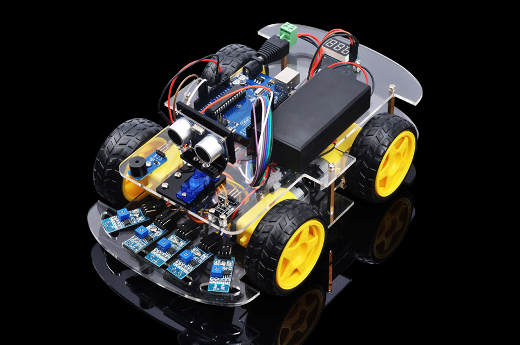 |
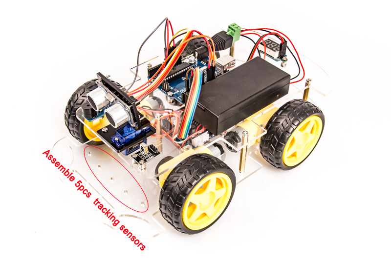
In this lesson, we will add 5 black/white tracking sensors to the framework built in Lesson 1. If you have not completed installation in Lesson 1, please review Lesson 1 |
The software in this lesson will read data from these 5 black/white tracking sensors and automatically guide the smart car to move along the black track line in the white ground. |
|
Device Name
|
picture
|
qty
|
Screw Number |
|
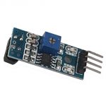
Tracking sensor module
|
 |
5
|
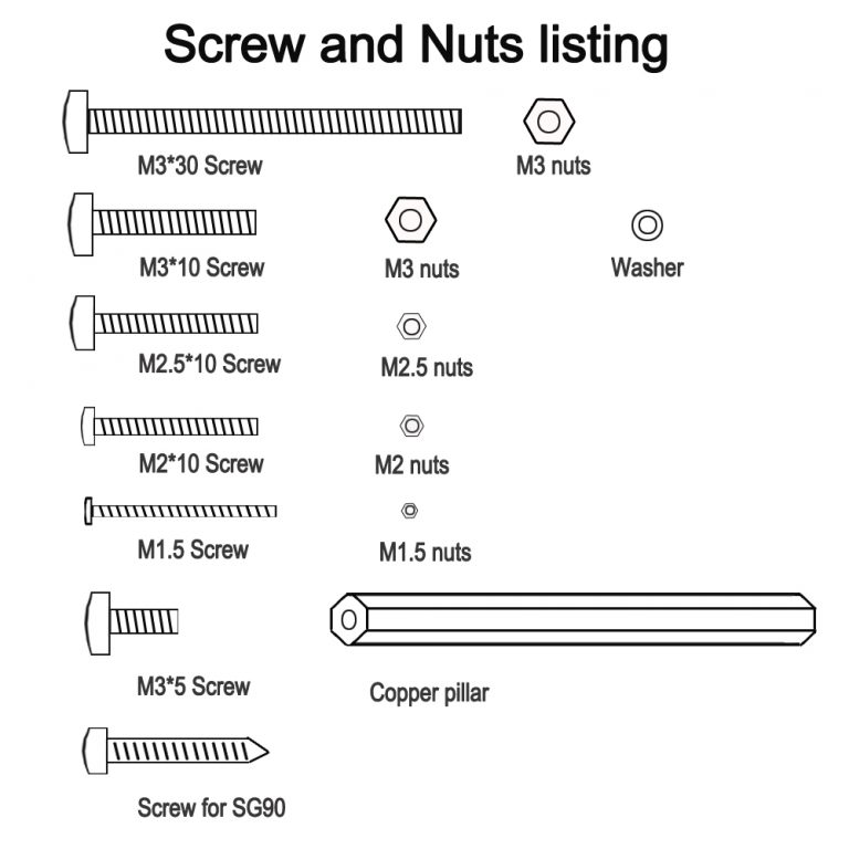
M3*10 screw x5 M3 nuts x5 |
|
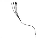
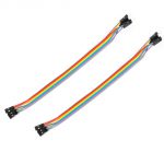
1pin male to 5 pins female jumper wires
|
 |
2
|
|
|
Lower chassis
|
|
1
|
M3*5 screw x5 Copper pillar x5 |
|
Upper chassis
|
|
1
|
M3*5 screw x5 |
|
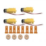
Gear Motor with wires
(Acrylic fastener for Gear Motor x8
Velocity encoder x4)
|
 |
4
|
M3*30 screw x8 M3 nuts x8 |
|
Wheel
|
 |
4
|
|
|
|
 |
1
|
M3*10 screw x4 M3 nuts x4 Transparent Washer x4 |
|
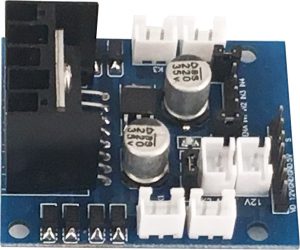
OSOYOO Model X motor driver module
|
 |
1
|
M3*10 screw x4 M3 nuts x4 Transparent Washer x4 |
|
Box for 18650 3.7V battery
|
 |
1
|
M3*10 screw x4 M3 nuts x4 |
|
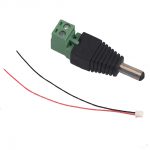
DC power connector with wires
|
 |
1
|
|
|
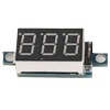
Voltage meter
|
 |
1
|
M3*10 screw x2 M3 nuts x2 Transparent Washer x2 |
|
Jumper wires(female to female)
|
 |
some
|
|
|
Jumper wires(male to female)
|
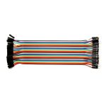 |
some
|
|
|
Cross screwdriver
|
 |
1
|
| 1) Install the smart car basic framework as per Smart Car Lesson 1. If you have already completed installation in Lesson 1, Lesson 2 and Lesson 3, just keep it as is. No need to remove any module installed in Lesson 2 and Lesson 3 . You can assemble tracking sensor modules into empty holes at the front of lower chassis . |
 |
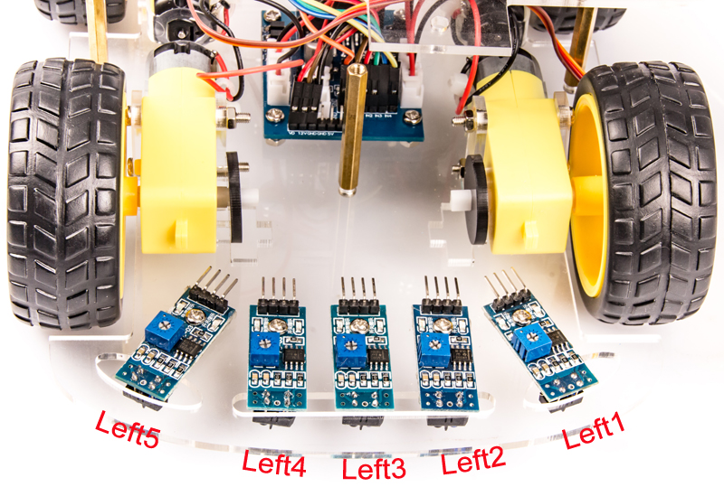
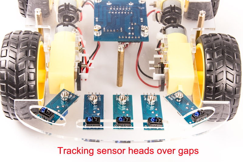
2) Fix tracking sensor module on lower chassis with 5pcs M3*10 screw and M3 nuts. Make sure that every sensor head is over the gaps at the front side of lower chassis so that the sensor can detect black lines in white ground. |
 |
 |
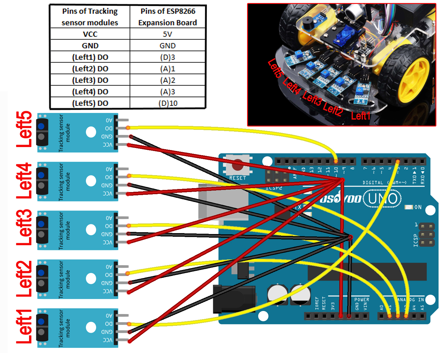
3) From left to right, connect the D0(D zero) pin in tracking sensor module to D3, A1, A2, A3, D10 pin in UNO board. Remember: DO NOT remove any existing wires installed in Smart Car Lesson 1 . Use 1pin male to 5 pins female jumper wires to connect VCC and GND of 5pcs tracking sensor modules. Connect VCC of tracking sensor module to 5V in UNO board, GND to GND. As the following photo shows: |
 |
| Step 1: Install latest Arduino IDE (If you have Arduino IDE version after 1.1.16, please skip this step). Download Arduino IDE from https://www.arduino.cc/en/Main/Software?setlang=en , then install the software. |
Step 2:Download Lesson 4 tracking smart car sample code, unzip the download zip file smartcar-lesson4.zip, you will see a folder called smartcar-lesson4. (Or upload the unziped folder in our CD instructions) |
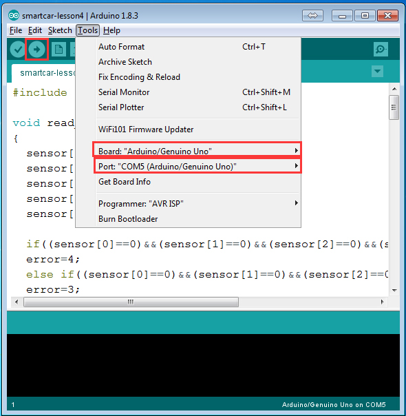
Step 3: Connect UNO R3 board to PC with USB cable, Open Arduino IDE -> click file -> click Open -> choose code "smartcar-lesson4.ino" in smartcar-lesson4 folder, load the code into arduino. |
 |
Step 4: Choose corresponding board/port for your project,upload the sketch to the board. |
 |
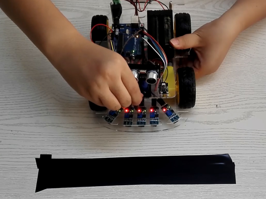
Step 5: Adjust the sensitivity of tracking sensor modules. Turn on and hold the car and adjust the potentiometer on the tracking sensor with cross screwdriver until you get the best sensitivity status: the signal indicate LED light will turn on when sensor is above white ground, and the signal LED will turn off when the sensor is above black track |
 |
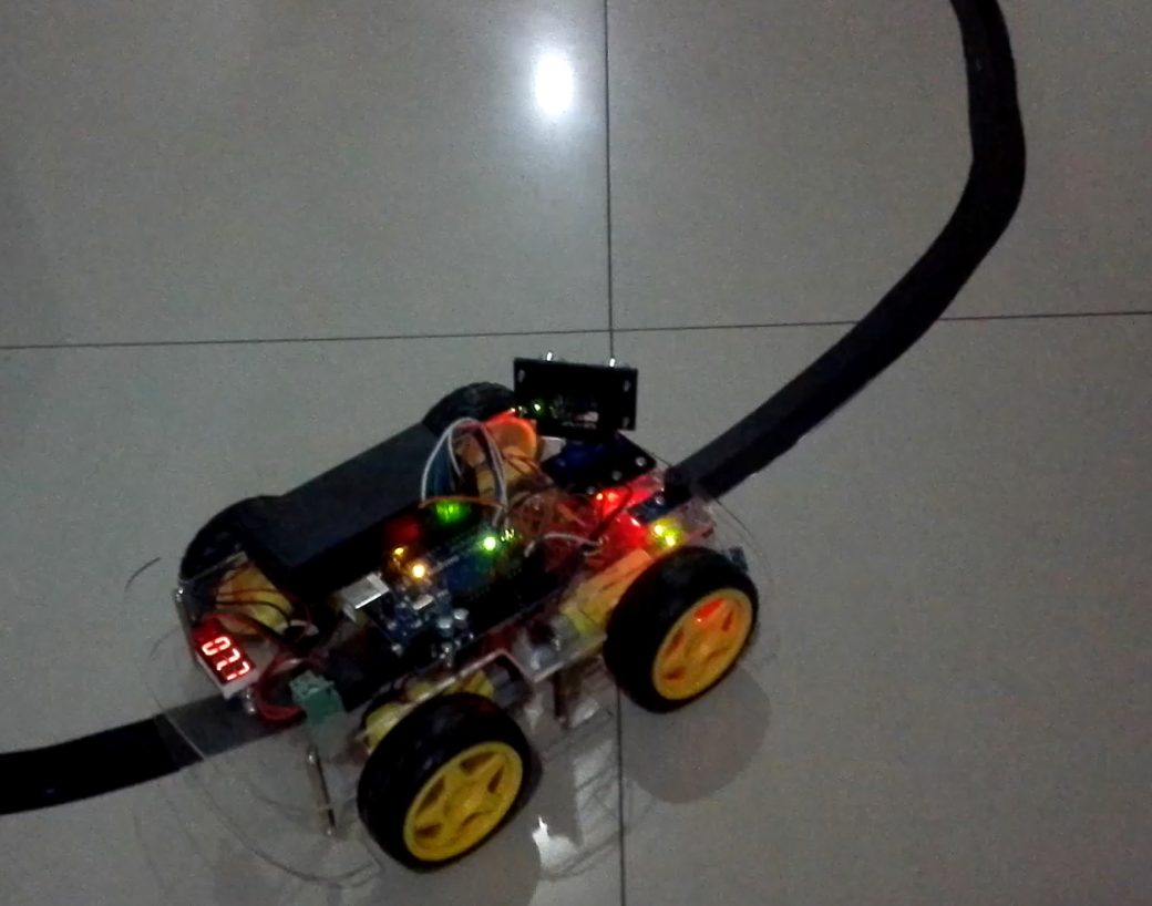
Prepare a 2-2.5cm black track in white ground(the width should not over the space between this two tracking sensor). |
 |
Please note, the bend angle of track can't be larger than 90 degree. If the angle is too large, the car will move out of the track. |
Turn on the car and put the middle of tracking sensor module facing over black track, and then the car will move along the black track. |
 |